US-guided injection of joints
James Collins, Robin Smithuis and Matthieu Rutten
Department of Radiology of the Medical Center, Leeuwarden, the Rijnland Hospital, Leiderdorp and the Jeroen Bosch Hospital, 's-Hertogenbosch, The Netherlands
Publicationdate
This article describes the application of Ultrasound guidance for diagnostic and therapeutic joint injections.
Ultrasound is a valuable alternative to procedures performed either blind or under fluoroscopic or CT guidance.
Shoulder

Glenohumeral joint
Anterior approach
In the anterior approach the patient is lying supine with the extended arm externally rotated (figure).
The transducer is placed ventrally parallel to the long axis of the subscapular tendon.
The grey line on the side of the transducer indicates the long axis.
Local anaesthetics are not needed if needles are used with a diameter of 21-gauge or thinner.
For joint aspirations one may need to use a larger bore needle due to high viscosity of the aspirate. In such cases local anaesthetics are indicated.
To facilitate injection of medication or contrast, one may use a connection tube in between the needle and the syringe, the latter being held and managed by an assistant.
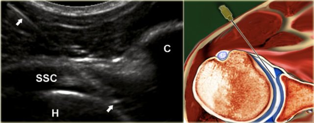 The landmarks one should look for are the medial contour of the humeral head and medial to this the coracoid process (C)
A 22-gauge, 50mm needle is used connected to a syringe containing the contrast media, held by an assistant who upon proper needle position injects 15-20 mL of the contrast medium.
The needle is advanced perpendicular to the medial edge of the humeral head, penetrating the subscapular tendon.
If one hits the cartilage of the humeral head, the needle should be pulled back 1 or 2 mm, slightly angled by about 15◦ and then advanced tangentially to the head into the joint with the bevel of the needle facing into the joint (figure).
No resistance to injection should be felt and one should see the contrast flow freely into the joint and if present into the subscapular recess.

Posterior approach
A. The needle is in the intra-articular position with the tip underneath the infraspinatus tendon (ISP) and posterior labrum (L) and bordering the hyaline cartilage (asterisks) of the humeral head.
B. Corresponding cadaver section showing the optimal needle track (white line).
C. Sonogram after injection of 15 mL contrast. The correct intra-articular position of the needle can be visualized real-time during injection, but is also confirmed by the 'comma'-like configuration of the posterior labrum (arrowheads), which is lifted by the intraarticularly injected fluid.
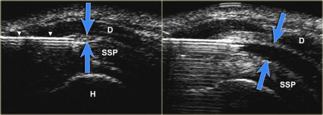 US-image showing a long axis view of the supraspinatus tendon (SSP). The advancing needle under real-time US-guidance has entered the subacromial bursa between the deltoid and SSP-muscle. Dilatation of the subacromial–subdeltoid bursa after injection of 5 mL fluid (blue arrows).
Subacromial bursa
The subacromial-subdeltoid bursa is a synovial lined space, which contains no observable or only a minimal amount of fluid.
The bursa consists of two bursal leaves. The outer and inner leaves are fused with the deltoid muscle fascia and rotator cuff, respectively. The bursal leaves can easily glide over each other, thus facilitating the range of movement of the shoulder.
Blind subacromial injection of drugs into the subacromial bursa is a frequently performed therapy by general practitioners and orthopedic surgeons. The incidence of injections that miss the subacromial bursa range from 12% to 70%.
Elbow

For injection of the elbow the patient is supine with the arm in 90◦ flexion, raised and resting on a cushion. The joint space between the radial head and the capitulum is easily palpated. The hand is pronated or may be turned into the thumb up position, which is necessary to open the joint maximally.
The transducer is placed over the joint visualizing the joint space. The needle (22 gauge, 30 mm) is directed at a slight craniocaudal angle on the dorsolateral side of the joint toward the joint space aiming toward the articular surface of the radial head.

When seen to have entered the joint and upon feeling the cartilage of the radial head, the needle is slightly pulled back to ensure that the bevel is free from the cartilage and facing into the joint.
5-8 mL of contrast media is injected. No resistance to injection should be felt.
Wrist and hand

Radiocarpal joint
The patient is supine with the wrist resting flexed over a 45◦ sponge or a rolled-up towel.
In some cases it may be helpful to hold the wrist in ulnar deviation in order to open the joint space even more.

The space between the radius and the scaphoid is identified on ultrasound.
A 23-25-gauge, 30 mm needle is advanced under ultrasound guidance into the joint directed toward the articular surface of the radius until one feels contact with the radius.
After ensuring that the tip of the needle is free from the radial cartilage 2-4 mL contrast is injected.
The bevel of the needle is facing toward the joint space and the contrast is seen to flow into the joint.
Distal radioulnar joint (DRUJ)
A linear array transducer is axially positioned dorsally over the distal radius and ulna. Along the short axis of the transducer a 23-25- gauge, 30 mm needle is inserted being directed from proximally to distally in a caudal direction. A total amount of 0.5-1 mL is injected according to rising pressure during injection.
Carpal, carpometacarpal and interphalangeal joints
Physicians and specialists routinely perform intra-articular punctures and injections on small wrist and finger joints to relieve joint effusion or to inject drugs.
The failure rate and frequency of occurrence of peri-articular injections are high: 15% - 32%, especially with the joints of the little finger and the DIP joints.
Unintended peri-articular drug injection moreover may affect the surrounding ligaments or tendons, leading to serious complications.
A dorsal approach using a 23-25-gauge needle is preferable. Although high-frequency linear array transducers with frequencies from 18 to 12 MHz are often used for scanning the superficial soft tissue structures of the wrist and hand, a small footprint transducer may allow better access to the small peripheral joints.
Generally, 0.5-1 mL of contrast material is instilled after confir- mation of correct needle placement.
Sacroiliac Joint
The sacroiliac joint has been implicated as a source of low back and lower extremity pain, which is thought to be caused by sacroiliitis.
Treatment consists of intra-articular injection of corticosteroids. Diagnostic injections or blocks are frequently performed, to distinguish between the probable causes of low back pain, because in 15-25% this is generated by the SI joint.
Upper level SI joint injection
The axially orientated transducer is moved from the level of the fifth lumbar vertebra caudally, depicting the dorsal surface of the sacrum with the median and lateral sacral crest, the gluteal surface of the ilium, and the first posterior sacral foramen.
The needle is inserted along the short axis of the transducer into the hypoechoic cleft located between the surface of the sacrum and the contour of the ilium. Angulations of needle insertion are adjusted to the orientation of the hypoechoic cleft of the SI joint, which presents cranially a more medial to lateral orientation, and caudally a more vertical orientation.
Lower level SI joint injection
From the upper level the transducer is moved downward by delineation of the median and lateral sacral crest, at the dorsal surface of the sacrum and the gluteal surface of the ilium until the second posterior sacral foramen is visualized.
As with the upper level, the needle is inserted into the hypoechoic cleft between the sacrum and ilium.
Hip

The patient is placed supine. The leg is held in slight endorotation and abduction thereby reducing tension on the capsular structures and moving the iliopsoas tendon and bursa medially out of the intended needle path.
Preferably a 5-3.5 MHz curved array transducer is used, which provides the necessary penetration depth.
Usually a 21 gauge needle with a length of 9 cm is used for the average adult. In smaller adults or children a 23-gauge, 5 cm hypodermic needle might be used.
Local anaesthetic may be injected prior to the main injection but this entails extra manipulation as well as non-contrast fluid (anaesthetic) in the joint leaving less room for the contrast in the limited joint space as well as possibly 2 punctures.
The needle may inadvertently be withdrawn from the joint after anaesthetic injection during the switch to connect the syringe with contrast. This could be avoided by using a three-way connector between the two syringes containing the anaesthetic and the injection fluid (contrast or medication).
The needle is advanced at a caudo-cranial angle along the long axis of the transducer aiming for the anterior recess near the junction of the femoral neck with the femoral head (see US and illustration).
The bevel of the needle should be facing toward the joint.
When the needle makes contact with the femoral head-neck junction it is slightly retracted to prevent inadvertently injection underneath the synovial fold of the hip joint capsule (see drawing).
If correctly positioned within the joint capsule, 10-15 mL contrast media or medication is injected and the anterior recess will distend by the injected fluid confirming the intra-articular positioning.
Knee

Indications for CT or MR arthrography of the knee are evaluation of the post-operative meniscus, query intra-articular bodies, evaluation of the stability of osteochondral lesions and evaluation of articular cartilage. One may also be requested to inject medication such as corticosteroids and/or a local anaesthetic.
For injection we do not use ultrasound guidance but use the standard "blind" procedure introducing the needle (21-gauge, 50 mm) behind the patella using a lateral midpatellar approach.
The patella is lateralized and the needle introduced from the mid lateral side aiming toward the centre of the patella indicated by the left forefinger.
The needle is introduced horizontally aiming posterior to the centre of the patella until one makes contact with the lateral patellar facet or the lateral femoral condyle and when felt to be in the joint 40 mL contrast media is injected.

Prior to CT or MR one can choose to apply a tight bandage above the patella thereby forcing contrast from the suprapatellar recess into the joint space proper.
Ankle and foot
 The foot is slightly plantar flexed. The long axis of the transducer is indicated by the grey line on the side, being in a sagittal plane.
Tibiotalar joint
CT or MR arthrography may be used to query ligamentous, osteochondral or chondral injury, eval- uation for free bodies or query stability of ostechondral lesions.
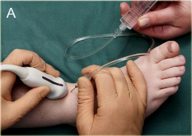
For injection of the ankle (tibiotalar joint) the patient is supine with the foot in slight plantar flexion.
The medial side of the tibiotalar joint is investigated anteriorly with ultrasound to deter- mine a suitable place for injection, at the same time checking for any excessive joint fluid.
We use a small curved array 8 MHz transducer but if preferred one can use an 18-12 MHz linear array transducer. The long axis of the probe is held in a sagittal plane.
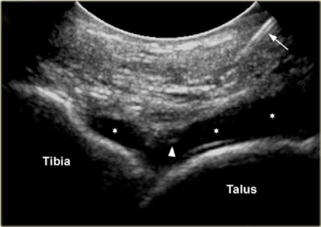 Sonogram showing the needle (arrow) and the needle tip (arrowhead) and the injected contrast media in the tibiotalar joint.
The needle, usually 22-gauge (length: 30 mm), is introduced in line with the long imaging axis of the transducer on the medial side of the anterior joint space, medial to the anterior tibial ligament, avoiding ligaments and vessels.
One should identify the talar dome and the overhanging anterior tibial lip. The needle is angled caudo-cranially into the joint under the ventral lip of the distal tibia aiming for the articular surface of the distal tibia.
Contact is felt and once again one ensures that the needle tip is free from the tibial cartilage and that the bevel is facing into the joint.

8-10 ml of contrast is injected into the tibiotalar joint and one sees the anterior capsule swells up with the fluid.
There should be no resistance to injection or pain experienced by the patient.
Posterior subtalar joint
The subtalar or talocalcaneal joint is composed of 3 facets: a broad posterior facet representing the primary articulating surface, a medially located middle facet in which the sustentaculum tali articulates with the medial process of the talus, and an anterior facet. Subtalar arthrography may be performed via an anterolat- eral, posterolateral or posteromedial approach. 2-4 ml of contrast material is injected into the posterior subtalar joint.
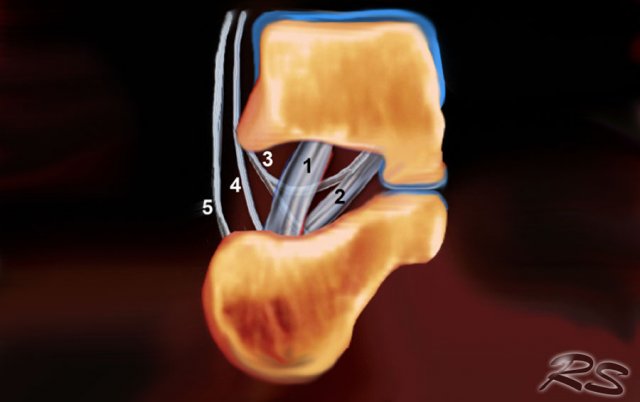 Schematic drawing in a coronal view of the right sinus tarsi. Displayed are the course and attachment sites of the cervical ligament (1); the interosseous talo- calcaneal ligament (2); and the medial (3), intermediate (4), and lateral (5) roots of the inferior extensor retinaculum.
Sinus tarsi
The sinus tarsi is a cone-shaped cavity that courses in a postero- medial to anterolateral direction. It is located in the lateral aspect of the foot between the neck of the talus and the anterosuperior surface of the calcaneus.
The tarsal sinus continues medially as the tarsal canal, which is a funnel-shaped space between the talus and the calcaneus.
It contains fat, an arterial anastomosis, joint cap- sules, nerve endings, and five ligamentous structures-the medial, intermediate, and lateral roots of the inferior extensor retinaculum; the cervical ligament; and the interosseous talocalcaneal ligament (figure).

This space can be the cause of foot pain in the sinus tarsi syn- drome. The first step in treatment is infiltration of the sinus tarsi with a mixture of Depomedrol and local anaesthetic (Lidocaine). This can be challenging for the surgeon in a non-guided approach but is reasonably easily and accurately achieved with ultrasound guidance.
US-guided injection of the sinus tarsi at the right-hand side with a lateral approach. The transducer is held in a coronal oblique plane. The needle is introduced along the long axis of the transducer.

The sinus tarsi can easily be visualized using ultrasound.
The patient turns onto the contralateral side laying the foot to be treated with its medial surface against the table top, the lateral side of the foot being uppermost.
The transducer is held in a coronaloblique plane with regards to the foot.

The sinus tarsi is identified as a triangular space between the anterior process of the calcaneus and the talar neck.
The tip of the needle (arrow head) is seen within the cone shaped sinus tarsi, which is bordered by the talus (T) and calcaneus (C).

Depending on the degree of inflammation there may be hyperemia of the space and there may be intervening vessels visible, which one wishes to avoid. This is relatively easy, especially with colour doppler
Volumes of injection

Click on the image below to look at the video of Medical Action Myanmar (MAM), an NGO run by Frank Smithuis and Nini Tun.
MAM has 12 clinics and 2100 community health workers all over Myanmar.
You can also visit the website of MAM
All donations are extremely well spend.